
A laser cutting cell loses money in two places: the cut, and everything that happens before it. When an operator drags a 3,000 × 1,500 mm steel sheet onto the bed by hand, the laser idles while two people lift, and material that has already been paid for picks up scratches before it is cut. A vacuum sheet metal lifter solves that — but only if it is specified against your sheets rather than picked from a catalogue page. This guide walks through the eight decisions that decide whether a lifter actually feeds your laser or just hangs above it, using the real engineering documents behind a laser-feeding vacuum lifter: beam and cross-beam dimensions, suction force calculations, overhang limits, and the safety figures that have to appear on the datasheet.
Laser feeding is a specific duty, and it is worth separating from general sheet handling. A warehouse lifter moves panels between stations. A laser-feeding lifter must place a sheet flat, aligned and undamaged on the bed, at a fixed cycle, usually by one operator, and it must do so while the laser’s own cycle time is the thing being protected. That difference changes the answers to almost every question below — pad layout, dead weight, overhang, control mode, and how the equipment is powered.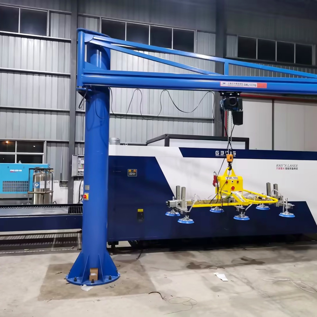
Table of Contents
- Start from the Sheet List, Not the Machine
- Apply the Overhang Rule Most Buyers Miss
- Do the Suction Force Math Yourself
- Check Vacuum Performance and Power-Failure Holding
- Examine Pad Layout, Adjustment and Surface Protection
- Confirm Cycle Time and Control Sequence
- Match Power Supply and Crane Integration
- Read the Documents the Supplier Should Give You
- FAQs
- Conclusion
1. Start from the Sheet List, Not the Machine {#sheet-list}
Four numbers about the material determine the lifter: maximum sheet length, maximum sheet width, maximum thickness, and the weight of the heaviest sheet you will routinely lift. Capacity sets the frame, the beam lengths, the pad count and the dead weight — and dead weight is what your jib or rail carries before a sheet is even attached.
The table below is built from actual technical proposals for laser-feeding lifters, and it shows why “what capacity do you need” is the wrong first question:
| Model | Max load | Sheet range it was specified for | Main beam | Cross beam | Pad dia. / count | Power |
|---|---|---|---|---|---|---|
| BLA400-6-T | 400 kg | 3,000 × 1,500 mm, 0.8–15 mm | 2,000 mm | 800 mm | 230 mm / 6 | 380 V, 50 Hz, 3-phase |
| BLA800-8-T | 800 kg | 3,000 × 1,500–1,800 mm, 0.6–15 mm | 2,000 mm class | 800 mm class | 300 mm / 8 | 415 V, 50 Hz, 3-phase |
| BLA1000-8-T | 1,000 kg | 1,000–3,000 × 1,250–1,500 mm, 2–20 mm | — | — | — | 380 V, 50 Hz, 3-phase |
| BLA1500-8-T | 1,500 kg | 3,000 × 1,500 mm, up to 20 mm | 2,000 mm | 800 mm | 300 mm / 8 | 230 V, 50 Hz, 1-phase |
| BLC1500-8-T | 1,500 kg | 6,000 × 2,000 mm, 3–16 mm | 5,000 mm (1,100 + 2,800 + 1,100) | 800 mm | 300 mm / 8 | 380 V, 50 Hz, 3-phase |
Read the table for the signal rather than the numbers. The same 1,500 kg capacity appears twice with completely different geometry — a 2,000 mm beam for 3,000 mm sheets, and a 5,000 mm telescopic beam for 6,000 mm sheets. Capacity alone tells you how much weight the machine can hold; beam length tells you whether the sheet is supported along its length. A 1,500 kg lifter with a 2,000 mm beam cannot properly support a 6,000 mm sheet, even though the weight is within rating.
The second signal: pad diameter grows with load class — 230 mm pads on the 400 kg unit, 300 mm pads on the 800 kg and 1,500 kg units. Pad area is what converts vacuum into holding force, so a supplier quoting a high capacity with small pads is either using more pads than listed or understating the requirement.
Tip: send your sheet list — length, width, thickness, material, heaviest routine sheet — and ask for the beam and cross-beam dimensions in the reply. If the answer only contains a capacity figure, the lift has not been engineered yet.
2. Apply the Overhang Rule Most Buyers Miss {#overhang}
This is the specification that separates a proposal written by an engineer from a quotation written by a salesperson, and almost no buyer asks about it.
Sheet metal is not rigid. When a vacuum lifter picks a plate, the portion of the plate extending beyond the outermost suction pads hangs unsupported, and it deflects under its own weight. Beyond a certain length, that deflection becomes permanent deformation — the sheet is bent before it ever reaches the laser, and the cut is scrap.
The engineering documents behind the BLA400-6-T state the limit explicitly:
- Minimum plate thickness: 3 mm
- Maximum overhang: L = 1,016 mm
- Stated consequence if exceeded: irreversible permanent deformation of the board
Two things follow for your selection. First, thin sheets are the constraint, not heavy ones. A 3 mm sheet on a 3,000 mm beam overhangs much further relative to its stiffness than a 12 mm sheet, so if your work mix includes thin material, the overhang figure is what decides whether you need more pads, a longer beam, or a different model. Second, the overhang limit is calculated against the minimum thickness in your range — which is why a supplier should ask for your thickness range, not just your maximum.
Ask for the overhang figure in writing, and ask which thickness it was calculated against. A proposal that states a maximum overhang without stating the thickness it applies to has not done the calculation.
Tip: if your sheets are routinely longer than the beam plus twice the overhang allowance, you are looking at a telescopic-beam model (BLC series) rather than a fixed-beam BLA — that is precisely the difference between the 2,000 mm and 5,000 mm rows in the table above.
3. Do the Suction Force Math Yourself {#suction-force}
You do not need to trust the capacity plate. The holding force of a vacuum lifter can be calculated from pad geometry and vacuum level, and doing it once tells you whether the specification is real.
The published calculation for a 230 mm pad at 60% vacuum works like this:
- Effective area of one pad: 0.115 × 0.115 × 3.14 (radius in metres, squared, times π)
- Design pressure: 0.6 bar — that is, the 60% vacuum figure used for the safety calculation, not the 85% peak
- Theoretical holding force per pad: (0.115 × 0.115 × 3.14) × 0.6 × 10,000 ≈ 249 kgf
- After applying the double safety factor: 249 ÷ 2 ≈ 124 kgf per pad
- Six pads: ≈ 700 kgf total holding capacity on a 400 kg rated lifter
Two lessons hide in that arithmetic. First, the calculation is done at 60% vacuum, not the 85% peak — the system reserves roughly 40% of its vacuum range so that a leak, a dirty pad or a partially sealed pad does not immediately put the sheet at risk. Second, the safety factor S > 2.0 is applied to the force, not just written on the datasheet: a 400 kg lifter with six 230 mm pads holds roughly 700 kgf, which is a real margin rather than a marketing claim.
What to ask, and what the answer should look like:
| Question | The answer you want |
|---|---|
| What vacuum level is the holding force calculated at? | The alarm/design value (e.g. 60%), not the peak |
| What is the theoretical force per pad, and the pad diameter? | A number per pad plus the diameter, so you can verify |
| How many pads are in contact at your smallest sheet? | A count, not the maximum pad count |
| What safety factor is applied, and in which direction? | S > 2.0 stated for horizontal lifting |
That last row matters more than it looks. A lifter rated S > 2.0 for horizontal handling is not automatically rated for a tilted pick — if your process ever lifts at an angle, the rating has to be stated for that orientation.
Tip: run the math for your smallest sheet, not your largest. Six pads hold 700 kgf when all six are sealed against the plate; on a narrow sheet where two pads hang in air, the usable force drops unless those pads are valved off.
4. Check Vacuum Performance and Power-Failure Holding {#vacuum}
Five figures belong on the datasheet. If any of them is missing, the proposal is incomplete.
| Parameter | Specification (BLA series documents) | Why it matters in a laser cell |
|---|---|---|
| Maximum vacuum | 85% vacuum, approx. 0.85 kgf | Working pressure available at the pads |
| Alarm pressure | 60% vacuum, approx. 0.6 kgf | Point at which the audible/visual alarm triggers |
| Safety factor | S > 2.0, horizontal lifting | Margin over rated load |
| Power-failure holding | > 20 min (one proposal states ≥ 30 min in its service section) | Time to set the sheet down safely |
| Continuous duty | ≥ 8 h | Shift-length operation without thermal derating |
The power-failure figure deserves its own paragraph, because it is the difference between a near-miss and an injury. When power is lost, holding depends on three things working together:
- an integrated vacuum reservoir — on these units the main beam itself functions as the vacuum tank, so the reserve travels with the beam rather than sitting in a separate vessel;
- a vacuum non-return valve, which seals the vacuum line automatically on power or pump failure so the sheet is not released;
- the alarm chain, which shows the pressure drop while there is still time to act.
Note the honest inconsistency in the source documents: the BLA400-6-T performance table states holding above 20 minutes, while the same proposal’s design-advantages and service sections state ≥ 30 minutes. If a specific holding time is critical to your risk assessment, ask for the figure against your exact model and configuration rather than accepting the highest number in the document.
Also confirm the working band. Normal operation runs at 85%, the alarm is set at 60%, and the system is designed so the pad set holds well below the working pressure. A proposal that lists only “maximum vacuum” without an alarm threshold has not told you when the operator will be warned.
Tip: ask what happens on a single pad failure — a torn seal on one pad of six. The answer should involve the other pads holding through their own valves, not a system-wide drop.
5. Examine Pad Layout, Adjustment and Surface Protection {#pads}
Capacity lifts the sheet. Pad layout decides whether it stays flat, and flatness is what lets the sheet sit properly on the laser bed and cut to tolerance.
What the documents behind these lifters specify, and what it means for you:
- Pads on movable cross-beams. Each pair of pads is mounted on a cross-beam that travels along the main beam, and each pad can slide along its cross-beam. This is how one lifter covers a range of sheet sizes instead of only the largest format — the adjustment range, not the pad count, is what you should compare.
- Individual pad isolation. Every pad carries its own manual ball valve, so pads beyond the edge of a small sheet can be closed off instead of hanging in air and bleeding vacuum. This single feature is what makes a large lifter behave correctly on a narrow plate.
- Spring dampers at each pad stem. When the sheet surface is uneven, the springs equalise contact force across the pads so that suction is uniform — the difference between lifting a flat sheet and lifting one that is slightly bowed from the stack.
- Non-marking rubber suction faces. The contact face is lined to prevent surface damage on visible or pre-finished material.
- Replaceable seals at low cost. Sealing rings are consumables; cheap, light and easy to replace is a maintenance-cost specification, not a minor detail.
- Swivel suction heads. Rotatable pad assemblies conform to contoured plates where a fixed head would only seal partially.
The numbers to compare across suppliers are pad diameter (230 mm versus 300 mm in the table above), pad count, adjustment travel along both beams, and whether isolation is per-pad or per-group. Per-group isolation is cheaper to build and less useful in a mixed-size work mix.
Tip: ask for a sketch of the pad layout overlaid on your smallest and largest sheets. Where pads fall outside the plate, they should be valved off; where they fall inside but near an edge, the overhang rule from section 2 applies.
6. Confirm Cycle Time and Control Sequence {#cycle}
In laser feeding the lifter’s cycle sets the cell’s real throughput, because the laser cannot cut while it waits for material. Two numbers decide it, and one sequence decides whether the operator can work safely.
- Suction and release: under 2 seconds each. The BLA400-6-T documents specify suction and release at less than 2 s, with the first suction of a cycle longer at about 10–15 seconds while the system pulls down the reservoir. That first-pick penalty is why cycle calculations based on 2 s per sheet are optimistic for short runs and closer to reality in continuous feeding.
- The control sequence matters as much as the speed. The documented sequence is: position the lifter over the sheet with the crane → push the manual slide valve forward to evacuate → when the preset vacuum is reached the green indicator lights and the buzzer falls silent, signalling ready-to-hoist → transport with the crane → depress the safety latch and pull the valve back to vent and release. A release that requires a deliberate two-action movement (latch plus pull) is a safety feature, not a delay.
- Manual slide valve versus remote. These units use a manual push-pull slide valve for suction and release, with the integrated control handle designed for one-hand operation. Remote control exists on other configurations of the same platform, but for laser feeding the manual valve is what gives fine positioning over the bed — confirm which control your machine actually ships with rather than assuming.
- Energy-saving pump cycling. Once target vacuum is reached the pump shuts off and restarts only when pressure decays past the threshold. That reduces energy use and pump wear, and it removes continuous pump noise from the cell.
Two supporting details are worth checking in the datasheet: the speed test result stated explicitly (plate applied ≤ 2 s, plate released ≤ 2 s), and whether the ready signal is both visual and audible — a green lamp alone is invisible to an operator wearing a face shield who is looking at the sheet edge.
Tip: ask for a video of the lifter cycling on a sheet of your size, including the alignment step over the bed. Positioning, not lifting, is where laser-feeding cycle time is actually lost.
7. Match Power Supply and Crane Integration {#power}
Power is the specification that most often goes wrong between quotation and commissioning. The proposals behind these lifters show three different site configurations for the same product family:
| Configuration | Where it applies | What to confirm |
|---|---|---|
| 380 V, 50 Hz, 3-phase | Common industrial sites | Phase count and tolerance (±15%) |
| 415 V, 50 Hz, 3-phase | Sites on 415 V distribution | Whether the pump motor is rated for 415 V or transformed |
| 230 V, 50 Hz, 1-phase | Smaller cells with single-phase available | Cable sizing and socket location at the cell |
Two other power topics come up in real proposals and are worth deciding early:
- DC and battery options. The same platform offers DC motor drive and a battery configuration — useful where a trailing cable across the loading area is a snag hazard, or where the lifter is shared between machines.
- Transformer matching. Because mains voltage differs by country and region, the transformer should be selected for your location rather than assumed. Send a photograph of the machine nameplate and the socket the lifter will use; a supplier who asks for it will configure correctly.
The integration question is separate from the power question, and it is the one buyers forget: the lifter does not include the crane. In these proposals the lifting equipment — driving crane or jib arm with crane — is explicitly provided by the client, and the proposal states the minimum crane capacity required (for example, jib crane max carrying capacity above 500 kg for a 400 kg lifter, or above 1,000 kg for a 1,000 kg lifter). The crane specification itself is a proper engineering document: rated capacity, duty class, lifting speed, rotation angle and power supply.
What to check on the crane side, using a real jib crane proposal as the template:
- Rated capacity above the lifter’s load plus its dead weight — not equal to it.
- Rotation angle and arm length — a 270° manual rotation with a 4 m arm and 2.2 m lifting height covers a single loading position; anything longer needs a rail system instead.
- Duty class — A3 to A5 class appears across these proposals; a laser cell running two shifts is not an A3 application.
- Hoist speeds — dual-speed hoisting (fast unloaded, slow loaded) is what allows precise placement without a slow cycle.
- Floor condition — the column imposes a point load, and the drawings state the ground-strength requirement (3 t/m² class appears in these documents). Confirm it before you pour or drill anything.
Tip: draw the cell in plan view — laser bed, sheet stack, operator position, column position — and mark the reach circle. Most bad installations are visible on that one drawing.
8. Read the Documents the Supplier Should Give You {#documents}
By this point you have enough to compare machines. The last filter is the paperwork, because a technical proposal is where a manufacturer shows whether it has engineering or only a price list.
A complete proposal for a laser-feeding lifter should contain all of the following. The list below is not aspirational — it is what the documents behind the BLA400-6-T actually include:
- Workpiece specification — material, maximum weight, length, width and thickness range, stated against a real inquiry.
- Site electrical configuration — voltage, frequency, phases, plus the crane capacity available.
- Equipment selection drawing — main beam length, cross-beam width, pad diameter and pad count, with the layout dimensioned.
- Performance table — maximum load, overall dimensions, power input, control mode, suction/release time, maximum and alarm pressure, safety factor, net weight, power-failure holding time.
- Design standard statement — CE EN 13155:2003, with design based on ASME B30-20-2006 and German UVV18, and the note that the main design indices exceed those standards.
- Safety factor derivation — the calculation at 60% vacuum with the 40% reserve explained, plus the overhang limit and the minimum plate thickness.
- Suction force calculation — per-pad theoretical force, the safety factor applied, and total holding force for the pad count.
- Spare parts list with brands — vacuum pump (capacity, power, max vacuum), pads (diameter, quantity), vacuum gauge (make and model), non-return valve, filter, ball valves, control handle, vacuum tank, warning unit, storage support, electrical box.
- Component function descriptions — what each part does, including which component seals the line on power failure and which one warns the operator.
- Design advantages — vacuum reservoir, adjustable pad/beam system, multi-point suction, alarm chain, individual pad isolation, spring dampers, energy-saving pump cycling, swivel heads, replaceable seals, surface treatment.
- Operating sequence — positioning, suction, transport, release, individual pad control.
- Delivery and service terms — assembly and acceptance testing at the manufacturer’s facility before shipment, lead time, warranty period, technical support availability, training, and consumables supply.
On the commercial terms, the documents set concrete expectations you can hold a supplier to: lead time of 1–2 weeks from the effective contract date, a 12-month warranty with parts repair or replacement at no charge, 24/7 technical support, complimentary preventive maintenance visits, free on-site training by certified engineers, and consumables at distributor pricing for the life of the equipment.
And the quality marks should be traceable, not decorative: CE certification EN 13155:2003 (certificate no. 1975120112 has appeared on these documents) and ISO 9001 quality system approval. Ask for the certificate PDF and check that the manufacturer name matches the quotation and the bank details.
For context on the supplier behind these documents: Shanghai Herolift Automation Equipment Co., Ltd has designed and built vacuum lifters since 2006, serves more than 60 industries and exports to more than 60 countries, with installations including heavy-capacity vacuum lifting systems at Shanghai Baosteel and exports to the United States, Canada, Australia, the European Union, East Asia and Africa.
FAQs {#faqs}
What capacity lifter do I need for a 3,000 × 1,500 mm laser bed?
Size by the heaviest sheet you routinely lift, then check the beam length against the sheet length. In the documents above, a 400 kg unit covers 3,000 × 1,500 mm sheets of 0.8–15 mm on a 2,000 mm beam, a 1,000 kg unit covers 1,000–3,000 × 1,250–1,500 mm of 2–20 mm, and a 1,500 kg telescopic unit covers 6,000 × 2,000 mm of 3–16 mm on a 5,000 mm beam. Capacity without beam length is only half the answer.
What is the overhang limit, and why does it matter?
Overhang is how far the sheet extends beyond the outermost suction pads. On the BLA400-6-T documents the maximum overhang is 1,016 mm at a minimum plate thickness of 3 mm, and exceeding it risks irreversible permanent deformation of the board. Always ask which thickness the overhang figure was calculated against — thin sheets are the constraint, not heavy ones.
How is the suction force calculated?
From pad area and design pressure: for a 230 mm pad at 0.6 bar (the 60% vacuum design figure), the theoretical force is about 249 kgf per pad. With the double safety factor applied, that is about 124 kgf per pad, or roughly 700 kgf across six pads on a 400 kg rated unit. The calculation is deliberately done at 60%, not the 85% peak, leaving about 40% vacuum reserve.
What safety factor should the lifter have?
S > 2.0 for horizontal lifting, stated on the datasheet. If your process ever lifts at an angle, the rating must be stated for that orientation — a horizontal rating does not automatically cover a tilted pick.
How long does the lifter hold if the power fails?
The BLA400-6-T performance table states more than 20 minutes, while the same proposal’s design-advantages and service sections state 30 minutes or more. Ask for the figure against your exact model and configuration. The reserve comes from an integrated vacuum reservoir — the main beam acting as the tank — plus a vacuum non-return valve that seals the line automatically.
How fast is the cycle?
Suction and release are specified at under 2 seconds each, with the first suction of a cycle taking about 10–15 seconds while the reservoir pulls down. That first-pick difference is why short-run cycle calculations are usually optimistic.
Do I need to buy the crane as well?
The lifter does not include the crane. In these proposals the lifting equipment — driving crane or jib arm with crane — is provided by the client, and the proposal states the minimum required crane capacity (for example above 500 kg for a 400 kg lifter, above 1,000 kg for a 1,000 kg lifter). The column also imposes a point load, so confirm the floor strength requirement from the drawings.
Which power configuration should I specify?
380 V three-phase is the common industrial configuration, 415 V three-phase suits 415 V distribution, and 230 V single-phase suits smaller cells. DC drive and battery configurations are available on the same platform — useful where a trailing cable is a snag hazard. Because voltage differs by region, the transformer is matched to your site rather than assumed.
Will one lifter handle both small and large sheets?
That is the purpose of movable cross-beams, sliding pads and per-pad ball valves: pads outside a small sheet are valved off so they do not bleed vacuum, and pads inside are positioned along both beams. Compare adjustment travel and isolation type (per-pad versus per-group) across suppliers — per-group isolation is cheaper and less useful in a mixed-size work mix.
What should the supplier’s technical proposal contain?
Workpiece specification, site electrical configuration, dimensioned equipment drawing, performance table, design standard statement, safety factor derivation, suction force calculation, spare parts list with brands, component function descriptions, operating sequence, and delivery/service terms. If a supplier cannot produce these, you are talking to a reseller.
Conclusion {#conclusion}
Selecting a vacuum sheet metal lifter for laser feeding comes down to eight decisions: start from the sheet list rather than the machine and read beam length as carefully as capacity; apply the overhang rule at your minimum thickness; verify the suction force arithmetic at design vacuum rather than peak; confirm the five vacuum figures including power-failure holding; examine pad layout, adjustment travel and per-pad isolation; check the cycle including the first-pick penalty and the two-action release; match the power configuration and size the crane for load plus dead weight with the floor condition confirmed; and require a technical proposal that contains the twelve documents above.
Do those eight things and the lifter becomes part of the cell. Skip them and it becomes another machine the operator works around.
HEROLIFT has designed and manufactured vacuum sheet metal lifters and handling systems in Shanghai since 2006, exporting to more than 60 countries. Send your sheet list, laser cell drawing and site voltage, and we will return a configured proposal with beam and pad layout, suction force calculation, performance figures and crane requirements for your application.
Contact HEROLIFT Email: melissa.men@herolift.cn Phone / WhatsApp: +86 21 64907850 · +86 13661991495 · Toll-free 400-628-1977 Address: No.149, Lane 150, Pingbei Road, Minhang District, Shanghai, China
HEROLIFT — vacuum sheet metal lifters, column cantilever vacuum cranes and handling equipment designed and manufactured since 2006. CE certification EN 13155:2003 (certificate no. 1975120112), ISO 9001 quality system approved, designed to German UVV18. Serving 60+ industries in 60+ countries.
Post time: Oct-20-2026